Politiche per la sicurezza (modificale con il modulo "Rassicurazioni cliente")
 Politiche per le spedizioni (modificale con il modulo Rassicurazioni cliente)
 Politiche per i resi merce (modificale con il modulo Rassicurazioni cliente)
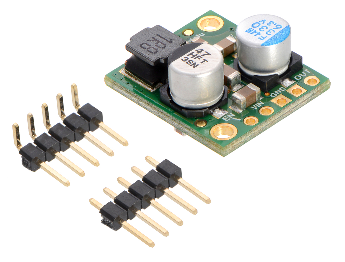
This small synchronous switching step-down (or buck) regulator takes an input voltage of up to 38 V and efficiently reduces it to 5 V. The board measures only 0.7″ × 0.8″, but it allows a typical continuous output current of up to 5 A. Typical efficiencies of 85% to 95% make this regulator well suited for high-power applications like powering motors or servos. High efficiencies are maintained at light loads by dynamically changing the switching frequency, and an optional shutdown pin enables a low-power state with a current draw of a few hundred microamp
The D24V50Fx family of step-down voltage regulators generates lower output voltages from input voltages as high as 38 V. They are switching regulators (also called switched-mode power supplies (SMPS) or DC-to-DC converters) with typical efficiencies between 85% and 95%, which is much more efficient than linear voltage regulators, especially when the difference between the input and output voltage is large. The available output current is a function of the input voltage and efficiency (see the Typical Efficiency and Output Current section below), but the output current can typically be as high as 5 A.
At light loads, the switching frequency automatically changes to maintain high efficiencies. These regulators have a typical quiescent (no load) current draw of less than 1 mA, and the ENABLE pin can be used to put the boards in a low-power state that reduces the quiescent current to approximately 10 µA to 20 µA per volt on VIN.
The modules have built-in reverse-voltage protection, short-circuit protection, a thermal shutdown feature that helps prevent damage from overheating, a soft-start feature that reduces inrush current, and an under-voltage lockout.
Features
This buck regulator has five connection points for four different connections: enable (EN), input voltage (VIN), 2x ground (GND), and output voltage (VOUT).
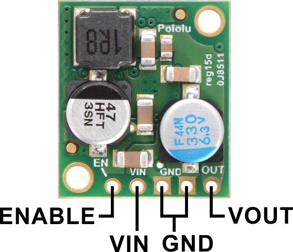 |
The input voltage, VIN, powers the regulator. Voltages between 4.5 V and 38 V can be applied to VIN, but for versions of the regulator that have an output voltage higher than 4.5 V, the effective lower limit of VIN is VOUT plus the regulator’s dropout voltage, which varies approximately linearly with the load (see below for graphs of dropout voltages as a function of the load).
The output voltage, VOUT, is fixed and depends on the regulator version: the D24V50F3 version outputs 3.3 V and the D24V50F5 version outputs 5 V.
The regulator is enabled by default: a 100 kΩ pull-up resistor on the board connects the ENABLE pin to reverse-protected VIN. The ENABLE pin can be driven low (under 0.6 V) to put the board into a low-power state. The quiescent current draw in this sleep mode is dominated by the current in the pull-up resistor from ENABLE to VIN and by the reverse-voltage protection circuit, which will draw between 10 µA and 20 µA per volt on VIN when ENABLE is held low. If you do not need this feature, you should leave the ENABLE pin disconnected.
|
|
The five connection points are labeled on the top of the PCB and are arranged with a 0.1″ spacing for compatibility with solderless breadboards, connectors, and other prototyping arrangements that use a 0.1″ grid. Either the included 5×1 straight male header strip or the 5×1 right angle male header strip can be soldered into these holes. For the most compact installation, you can solder wires directly to the board.
 |
|
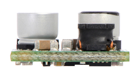
Pololu 5A Step-Down Voltage Regulator D24V50Fx, side view. |
|---|
The board has two 0.086″ mounting holes intended for #2 or M2 screws. The mounting holes are at opposite corners of the board and are separated by 0.53″ horizontally and 0.63″ vertically
| Size: | 0.7″ × 0.8″ × 0.35″1 |
|---|---|
| Weight: | 3.0 g1 |
| Minimum operating voltage: | 6 V2 |
|---|---|
| Maximum operating voltage: | 38 V |
| Continuous output current: | 5 A3 |
| Output voltage: | 5 V |
| Reverse voltage protection?: | Y |
| Maximum quiescent current: | 0.8 mA4 |
| PCB dev codes: | reg15d |
|---|---|
| Other PCB markings: | 0J8511 |