
Pololu G2 High-Power Motor Driver 18v25
 Politiche per la sicurezza (modificale con il modulo "Rassicurazioni cliente")
 Politiche per le spedizioni (modificale con il modulo Rassicurazioni cliente)
 Politiche per i resi merce (modificale con il modulo Rassicurazioni cliente)
"
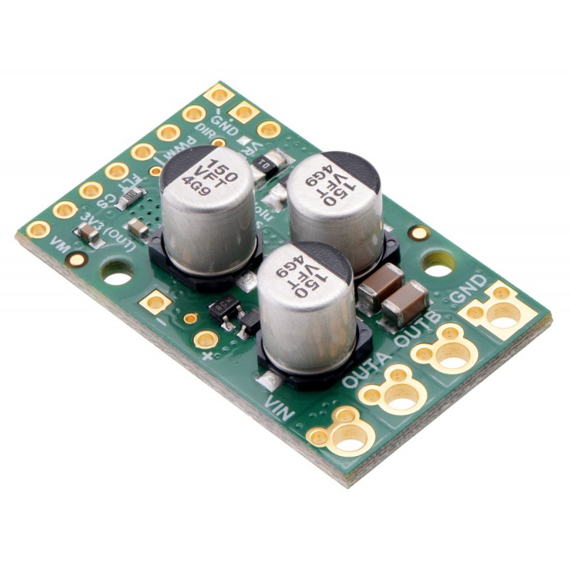
This discrete MOSFET H-bridge motor driver enables bidirectional control of one high-power DC brushed motor. The small 1.3? × 0.8? board supports a wide 6.5 V to 30 V voltage range and is efficient enough to deliver a continuous 25 A without a heat sink. Additional features of this second-generation (G2) driver include reverse-voltage protection along with basic current sensing and current limiting functionality.
The Pololu G2 high-power motor driver is a discrete MOSFET H-bridge designed to drive large brushed DC motors. The H-bridge is made up of one N-channel MOSFET per leg; the rest of the board contains the circuitry to take user inputs and control the MOSFETs. The absolute maximum voltage for this motor driver is 30 V, and higher voltages can permanently destroy the motor driver. Under normal operating conditions, ripple voltage on the supply line can raise the maximum voltage to more than the average or intended voltage, so a safe maximum voltage is approximately 24 V.
Note: Battery voltages can be much higher than nominal voltages when they are charged, so the maximum nominal battery voltage we recommend is 18 V (and use with 24 V batteries is not recommended) unless appropriate measures are taken to limit the peak voltage.
The versatility of this driver makes it suitable for a large range of currents and voltages: it can deliver up to 25 A of continuous current with a board size of only 1.3? × 0.8? and no required heat sink. The module offers a simple interface that requires as few as two I/O lines while still allowing for your choice of sign-magnitude or locked-antiphase operation. A current sense output gives an indicator of motor current, and the driver can limit the motor current to a configurable threshold. The power supply inputs feature reverse-voltage protection, while integrated detection of various fault conditions helps protect against other common causes of catastrophic failure; however, please note that the board does not include over-temperature protection.
The G2 High-Power Motor Driver 18v25 is a second-generation successor to our original High-Power Motor Driver 18v25. The G2 driver is much smaller than the original, but its interface and output capabilities make it a near drop-in replacement in typical applications. See “Differences from original high-power motor drivers” below for more details.
| PIN | Default State | Description |
|---|---|---|
| VIN | This is the main 6.5 V to 30 V (absolute max) motor power supply connection. | |
| VM | This pin gives you access to the motor power supply after reverse-voltage protection. It can be used to supply reverse-protected power to other components in the system, but it should not be used for high currents. This pin should only be used as an output. | |
| +, ? | These pads are intended for a power supply capacitor (they are connected to VM and GND, respectively). | |
| 3V3 (out) | This regulated 3.3 V output provides a few milliamps, which can be useful as a reference or for powering small external circuits. This output should not be connected to other external power supply lines. It is disabled when the driver is in sleep mode. Be careful not to accidentally short this pin to the neighboring VM pin while power is being supplied as doing so will instantly destroy the board! | |
| GND | Ground connection for logic and motor power supplies. | |
| OUTA | Motor output pin A (connects to one terminal of a DC motor). | |
| OUTB | Motor output pin B (connects to the other terminal of a DC motor). | |
| PWM | LOW | Pulse width modulation input: a PWM signal on this pin corresponds to a PWM output on the motor outputs. |
| DIR | LOW | Direction input: when DIR is high, current will flow from OUTA to OUTB; when it is low, current will flow from OUTB to OUTA. |
| SLP | HIGH | Inverted sleep input: This pin is pulled high by the driver board, enabling the driver by default; drive SLP low to put the motor driver into a low-power sleep mode. |
| FLT | Fault indicator: This open-drain output is driven low when a fault has occurred. See below for details. In order to use this output, you should externally pull this pin up to your system’s logic voltage. | |
| CS | Current sense output: This pin outputs a voltage proportional to the motor current when the H-bridge is driving (but not while it is braking, including when current limiting is active). The output voltage is about 10 mV/A plus a 50 mV offset. | |
| VREF | Reference voltage input: An additional resistor can be connected between this pin and GND to lower the current limiting (chopping) threshold. Without an additional resistor, the current limit defaults to about 60 A. See below for details. |
| Size: | 1.3? × 0.8? |
|---|---|
| Weight: | 5.0 g1 |
| Motor channels: | 1 |
|---|---|
| Minimum operating voltage: | 6.5 V |
| Maximum operating voltage: | 30 V2 |
| Continuous output current per channel: | 25 A3 |
| Current sense: | 0.01 V/A |
| Maximum PWM frequency: | 100 kHz |
| Minimum logic voltage: | 1.8 V |
| Maximum logic voltage: | 5.5 V |
| Reverse voltage protection?: | Y |
"

Pololu G2 High-Power Motor Driver 18v25