

Pololu G2 High-Power Motor Driver 24v13
 Politiche per la sicurezza (modificale con il modulo "Rassicurazioni cliente")
 Politiche per le spedizioni (modificale con il modulo Rassicurazioni cliente)
 Politiche per i resi merce (modificale con il modulo Rassicurazioni cliente)
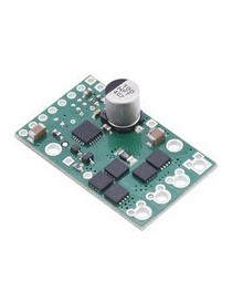
This discrete MOSFET H-bridge motor driver enables bidirectional control of one high-power DC brushed motor. The small 1.3? × 0.8? board supports a wide 6.5 V to 40 V voltage range and is efficient enough to deliver a continuous 13 A without a heat sink. Additional features of this second-generation (G2) driver include reverse-voltage protection along with basic current sensing and current limiting functionality.
The Pololu G2 high-power motor driver is a discrete MOSFET H-bridge designed to drive large DC brushed motors. The H-bridge is made up of one N-channel MOSFET per leg; the rest of the board contains the circuitry to take user inputs and control the MOSFETs. The absolute maximum voltage for this motor driver is 40 V, and higher voltages can permanently destroy the motor driver. Under normal operating conditions, ripple voltage on the supply line can raise the maximum voltage to more than the average or intended voltage, so a safe maximum voltage is approximately 34 V.
Note: Battery voltages can be much higher than nominal voltages when they are charged, so the maximum nominal battery voltage we recommend is 28 V unless appropriate measures are taken to limit the peak voltage.
The motor and motor power connections are on one side of the board, and the control connections (1.8 V to 5 V logic) are on the other side. The motor supply should be capable of supplying high current. There are two options for making the high-power connections (VIN, OUTA, OUTB, GND): large holes spaced 5 mm apart, which are compatible with the included terminal blocks, and pairs of 0.1?-spaced holes that can be used with perfboards, breadboards, and 0.1? connectors.
| PIN | Default State | Description |
|---|---|---|
| VIN | This is the main 6.5 V to 40 V (absolute max) motor power supply connection. | |
| VM | This pin gives you access to the motor power supply after reverse-voltage protection. It can be used to supply reverse-protected power to other components in the system, but it should not be used for high currents. This pin should only be used as an output. | |
| +, ? | These pads are intended for a power supply capacitor (they are connected to VM and GND, respectively). | |
| 3V3 (out) | This regulated 3.3 V output provides a few milliamps, which can be useful as a reference or for powering small external circuits. This output should not be connected to other external power supply lines. It is disabled when the driver is in sleep mode. Be careful not to accidentally short this pin to the neighboring V+ pin while power is being supplied as doing so will instantly destroy the board! | |
| GND | Ground connection for logic and motor power supplies. | |
| OUTA | Motor output pin A (connects to one terminal of a DC motor). | |
| OUTB | Motor output pin B (connects to the other terminal of a DC motor). | |
| PWM | LOW | Pulse width modulation input: a PWM signal on this pin corresponds to a PWM output on the motor outputs. |
| DIR | LOW | Direction input: when DIR is high, current will flow from OUTA to OUTB; when it is low, current will flow from OUTB to OUTA. |
| SLP | LOW | Inverted sleep input: This pin is internally pulled low, putting the motor driver into a low-power sleep mode. SLP must be driven logic high to enable the driver. Note: The SLP pin cannot be tied to the board’s 3V3 output to permanently enable the driver, since the 3.3 V output is disabled when the driver is in sleep mode. |
| FLT | Fault indicator: This open-drain output is driven low when a fault has occurred. See below for details. In order to use this output, you should externally pull this pin up to your system’s logic voltage. | |
| CS | Current sense output: This pin outputs a voltage proportional to the motor current when the H-bridge is driving (but not while it is braking, including when current limiting is active). The output voltage is about 40 mV/A plus a 50 mV offset. | |
| VREF | Reference voltage input: An additional resistor can be connected between this pin and GND to lower the current limiting (chopping) threshold. Without an additional resistor, the current limit defaults to about 30 A. See below for details. |
| Size: | 1.3"" × 0.8"" |
|---|---|
| Weight: | 3.3 g1 |
| Motor channels: | 1 |
|---|---|
| Minimum operating voltage: | 6.5 V |
| Maximum operating voltage: | 40 V2 |
| Continuous output current per channel: | 13 A3 |
| Current sense: | 0.04 V/A |
| Maximum PWM frequency: | 100 kHz |
| Minimum logic voltage: | 1.8 V |
| Maximum logic voltage: | 5.5 V |
| Reverse voltage protection?: | Y |
| PCB dev codes: | md31a |
|---|---|
| Other PCB markings: | 0J9257, blank white box |
"

Pololu G2 High-Power Motor Driver 24v13